Design Guide for Unattended Surveillance Sites and Monitoring Points
A comprehensive engineering reference for building reliable, remotely managed surveillance infrastructure at sites with no permanent on-site staff — covering power, communications, cameras, edge compute, security, and O&M.
System Overview
Unattended surveillance point design targets monitoring sites where no operators are stationed and maintenance is performed only by periodic patrols or remote support — examples include perimeter fences in wilderness areas, pipeline valve rooms and pumping stations, wind and solar farms, telecom towers, forest fire lookout points, traffic checkpoints, warehouse perimeters, and temporary construction sites. The engineering goal is not simply to "buy a good camera," but to build a site-level engineered capability so the station can see clearly, alarm accurately, stay connected, stay powered, be remotely maintainable, and recover quickly.
This guide covers point-level engineering including site selection, camera placement, power and energy systems, communications, grounding and lightning protection, enclosure and anti-vandal measures, edge compute, alarm strategy, remote O&M loop, and acceptance criteria. It does not replace detailed civil or structural design, but defines the interfaces and site engineering requirements that those disciplines must satisfy.
System Architecture
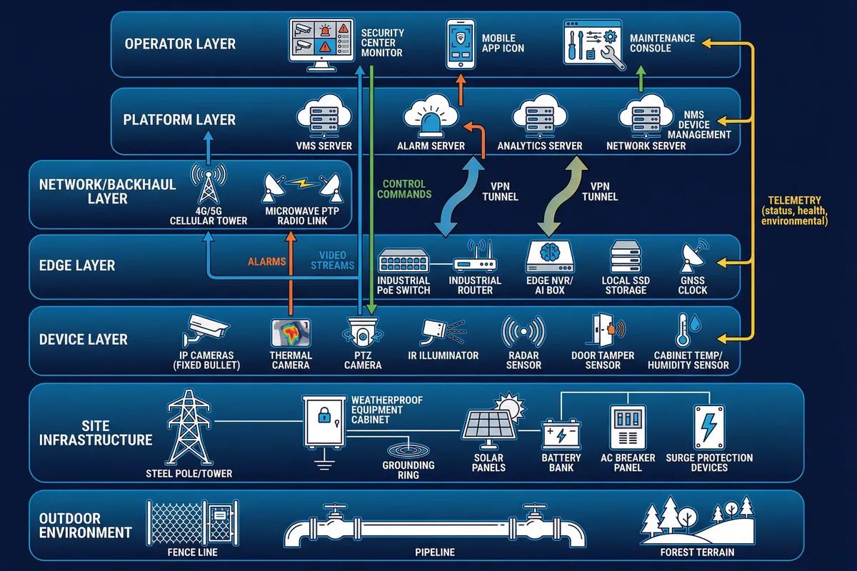
Figure 0.1: Overall unattended monitoring point architecture — layered from environment through site infrastructure, device, edge, network/backhaul, platform, to operator layers
The architecture follows a layered responsibility model. The site infrastructure layer ensures survivability through weatherproofing, anti-tamper measures, grounding, thermal design, and stable power distribution. The edge layer ensures continuity via local recording, event extraction, link monitoring, and graceful degradation. The platform layer ensures governance through access control, audit trails, retention policy, and alarm correlation. The O&M loop ensures recoverability by closing the alarm-to-ticket-to-dispatch-to-fix cycle.
Main Functions
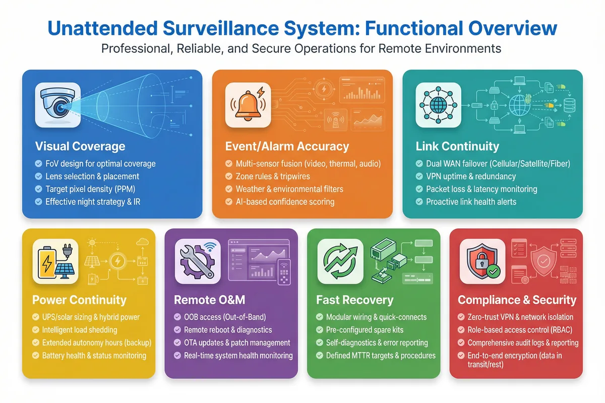
Figure 0.2: Functional overview map — seven core functional blocks covering visual coverage, alarm accuracy, link continuity, power continuity, remote O&M, fast recovery, and compliance & security
The seven core functions work in concert to maximize "useful uptime" of alarms and evidence video under harsh conditions with limited site visits, while minimizing lifecycle cost and mean time to recovery (MTTR). Each function has defined implementation mechanisms and acceptance checks that form the basis of the acceptance test plan described in Chapter 10.
Scope, Inputs & Outputs
The guide's scope spans point-level engineering from initial site assessment through to ongoing O&M. The key inputs and outputs are summarized below.
Site GIS & Location — coordinates, terrain, access constraints, flood risk, sun path for solar
Threat Model — intrusion, theft, fire, sabotage; defines camera placement and sensor selection
Coverage Objectives — identification vs detection distance; pixel density requirements
Available Utilities — AC mains, generator, solar feasibility; determines power system design
Site Survey Report — documented baseline for all design decisions and acceptance evidence
Network Topology + IP Plan — VLAN design, VPN policy, security segmentation diagram
Power System Sizing — wiring diagram, grounding plan, solar yield calculation, UPS sizing
Acceptance Checklist — test evidence, O&M schedule, spare parts plan, postmortem template
Chapter Navigation
This guide is organized into twelve chapters, each addressing a distinct engineering discipline. Use the navigation cards below or the left sidebar to access any chapter directly.
Key Dependencies & Core Value
Successful unattended surveillance deployment depends on five interdependent pillars: reliable power (AC or solar+battery), stable backhaul with failover, lightning protection and grounding, a secure enclosure, and a closed-loop O&M process. Weakness in any single pillar degrades the entire system's ability to deliver evidence-grade video and timely alarms.
Core Value: Maximizing "useful uptime" of alarms and evidence video under harsh conditions with limited site visits, while minimizing lifecycle cost and mean time to recovery (MTTR). The design philosophy is engineer the station, not just the camera — allocate budget first to power, backhaul, enclosure, and grounding before optimizing camera specifications.