System Components
Chapter 1 · Unattended Surveillance Site Design Guide
1.1 System Architecture
The unattended surveillance site is best understood as a self-contained engineered system with a clearly defined boundary. Within that boundary, every component must be selected and integrated to function reliably without human intervention for extended periods. The architecture diagram below illustrates the deployment boundary and the three internal zones that govern how components are grouped and prioritized during design, installation, and fault recovery.
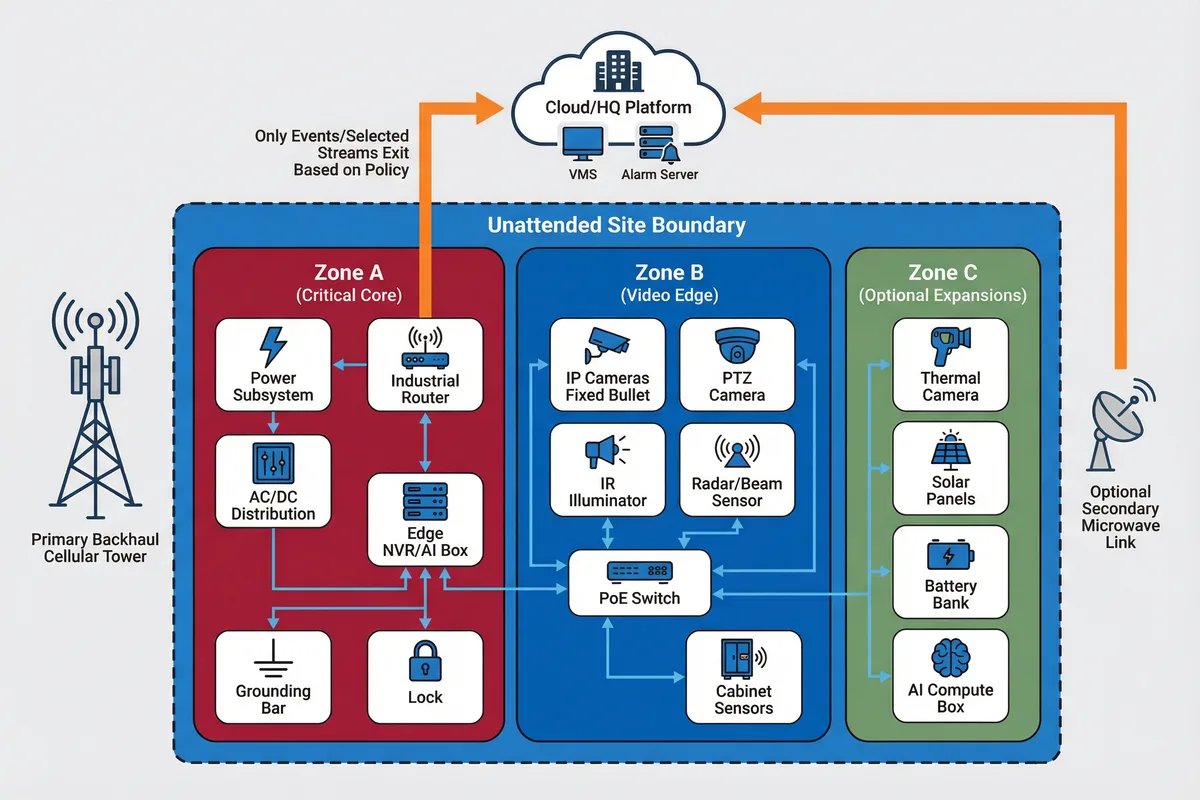
Figure 1.1: Single-site deployment boundary diagram — showing three internal zones (Critical Core, Video Edge, Optional Expansions) and external backhaul/platform connections
The three zones reflect a deliberate priority hierarchy. Zone A (Critical Core) contains the components whose failure causes total site loss — the power subsystem, router, NVR, and grounding infrastructure. These must receive the highest protection, redundancy, and monitoring priority. Zone B (Video Edge) contains the cameras, sensors, and PoE switch that deliver the primary security function. Zone C (Optional Expansions) contains enhancements such as thermal cameras, solar arrays, and AI compute boxes that improve performance but are not required for basic operation.
Module Relationships & Data Flows
Video Flow
Camera → PoE Switch → Edge NVR/AI → (a) local storage for continuous retention, (b) selective uplink to VMS based on policy (event clips or substream)
Telemetry Flow
Power controller/BMS, router, switch, cabinet sensors → NMS/IoT gateway → monitoring platform for health dashboards and predictive alerts
Control Flow
VMS/PTZ commands, configuration pushes, firmware updates → VPN tunnel → router → target devices; all commands authenticated and logged
Alarm Flow
Analytics events + sensor triggers → edge rules engine → alarm server → ticketing system + SMS/email notification → dispatch decision
Core / Optional / Supporting Classification
Every component in the system falls into one of three categories. This classification drives procurement priority, spare-kit composition, and the order in which components are restored after a fault.
| Category | Components | Design Implication |
|---|---|---|
| CORE | Camera(s), PoE switch, router, local recording, cabinet with lock, SPD + grounding, remote monitoring | Must be present at every site; failure = site loss; highest spare priority; monitored 24/7 |
| OPTIONAL | Radar/beam sensor, thermal camera, AI compute box, dual ISP, solar array, cabinet heater/fan, tamper mesh | Improves performance or resilience; selected based on threat model and environment; failure = degraded mode |
| SUPPORTING | Mounting structure, conduits, cabling, labeling, civil works, signage, access road | Enables installation and maintainability; must meet structural and environmental specs; not monitored electronically |
1.2 Components and Functions
Each component in the unattended surveillance system has a specific responsibility, defined inputs and outputs, key engineering metrics that must be verified during commissioning, and common mismatch risks that cause field failures. The component inventory board below provides a visual reference for the full device set, while the table that follows provides the engineering specification checklist used during procurement and acceptance.
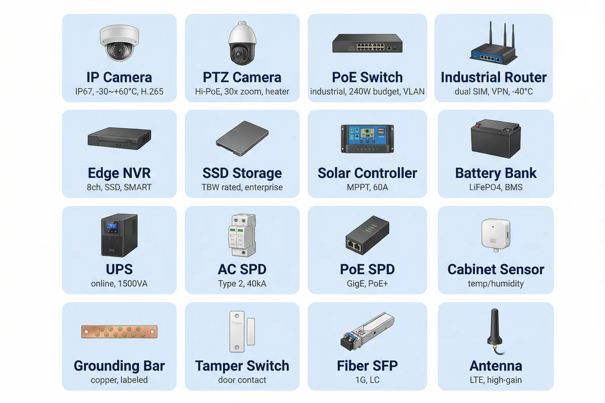
Figure 1.2: Component inventory board — all core and optional devices with key ratings including IP rating, temperature range, PoE budget, and throughput specifications
| Component | Responsibility | Key Engineering Metrics | Common Mismatch Risk |
|---|---|---|---|
| IP Camera (fixed) | Capture evidence video; provide identification-grade imagery at target distance | Resolution, low-light sensitivity (lux), WDR (dB), bitrate stability, operating temp range, IP rating | Wrong FoV → no identification at target distance; consumer-grade temp rating → winter failure |
| PTZ Camera | Long-range tracking, patrol scanning, incident zoom-in; alarm-triggered positioning | Optical zoom range, preset speed, heater/defog, wind tolerance, Hi-PoE requirement, position feedback accuracy | Underpowered PoE → reboot on PTZ move; no heater → fog/ice on lens; weak preset accuracy → missed target |
| PoE Switch (industrial) | L2 aggregation, PoE power delivery to cameras, VLAN segmentation, port watchdog | Total PoE budget (W), per-port PoE class, surge tolerance, operating temp, VLAN/QoS support, watchdog timer | PoE budget too low → brownout on PTZ move; no port watchdog → hung camera never recovers |
| Industrial Router | WAN backhaul, VPN termination, firewall, QoS, dual-SIM failover, remote management | VPN throughput (Mbps), dual SIM/eSIM, link failover time, GPS/NTP, watchdog, operating temp | No WAN failover → long outages on SIM issues; weak CPU → VPN bottleneck drops frames |
| Edge NVR / AI Box | Local recording, event tagging, store-and-forward, analytics model execution, clip packaging | Channel count, write endurance (TBW), SMART monitoring, AI model load, storage health telemetry | SSD wear-out unnoticed → silent data loss; insufficient channels → recording gaps |
| Local Storage (SSD/HDD) | Evidence retention for defined retention period; survives link outages | Total capacity (TB), TBW rating, SMART attribute monitoring, operating temp, vibration tolerance | Consumer HDD in vibration environment → early failure; no SMART monitoring → silent corruption |
| Cabinet + Lock | Physical protection of all electronics; weatherproofing, anti-tamper, thermal management | IP rating (min IP65), IK rating, corrosion class, internal volume, ventilation/heater options, tamper switch | Poor gland sealing → condensation kills electronics; no tamper switch → undetected intrusion |
| SPD + Grounding | Lightning and surge energy diversion; equipotential bonding across all metallic elements | Uc/Up ratings, Imax (kA), bonding conductor gauge, ground resistance target, SPD status indicator | "SPD without proper grounding" → SPD ineffective; long bonding leads → poor clamping performance |
| Power Subsystem | Continuous power delivery; autonomy during outages; safe shutdown; load priority management | Autonomy hours (Wh), low-voltage cutoff threshold, load shedding priority outputs, charger health, temp-compensated charging | Battery undersized for worst month → nightly shutdown; no low-voltage cutoff → deep discharge damage |
| Cabinet Sensors (temp/humidity/door) | Environmental health monitoring; tamper detection; early warning for condensation and overheating | Temperature accuracy (±1°C), humidity accuracy (±3% RH), door contact response time, sampling interval | No sensors → blind O&M; undetected humidity rise → corrosion; undetected overtemperature → device failure |
1.3 Working Principles
Startup Sequence
The startup sequence is designed to prevent inrush current overloads and ensure that security-critical services (VPN, time sync, recording) are established before cameras begin streaming. The sequence must be followed both after initial installation and after any power restoration event.
- Power subsystem stabilizes DC bus / UPS output; all SPDs are in place and verified operational.
- Router boots first and establishes the primary WAN link; VPN tunnel is brought up; NTP/GNSS time sync is confirmed.
- PoE switch powers cameras in staged sequence (staggered PoE enable) to avoid simultaneous inrush current.
- Edge NVR/AI starts recording; verifies storage health (SMART baseline) and available free space; loads analytics rule set.
- Platform receives "site online" heartbeat; baseline KPI snapshot is taken and stored for trend comparison.
Normal Operation
During normal operation, the system follows a continuous local-recording policy with selective uplink based on the configured backhaul policy. All cameras record locally at full resolution; only event clips or substreams are transmitted to the platform, preserving backhaul bandwidth for alarm responsiveness. The edge analytics engine continuously evaluates video and sensor inputs against the configured rule set, generating events that are forwarded with evidence clips and metadata.
Exception & Recovery Flows
The three most common abnormal chains are described below. Each chain includes the detection mechanism, system behavior during the fault, and the recovery procedure. These chains must be tested during acceptance and drilled quarterly during O&M.
Abnormal Chain A: Backhaul Outage
Detection: Router detects link loss via RSSI/RSRP drop, PPP down event, or sustained packet loss exceeding threshold.
Behavior: Automatic failover to secondary SIM/radio if configured; otherwise, continue local recording and queue events with timestamps for later upload.
Recovery: When link returns, buffered alarms are sent with original timestamps; optional clip upload resumes; platform marks outage duration and opens a ticket if duration exceeds SLA threshold.
Abnormal Chain B: Power Degradation / Low Battery
Detection: Battery SoC falls below configured threshold; DC undervoltage detected; charger fault alarm triggered.
Behavior: Staged load shedding in priority order — IR illuminator off → PTZ patrol suspended → uplink bitrate reduced → last resort: keep only router + one camera active.
Recovery: Once SoC recovers above restoration threshold, loads are re-enabled in reverse priority order; storage integrity is verified; platform raises a "power incident report" for O&M review.
Abnormal Chain C: Camera Tamper / Vandalism
Detection: Video occlusion analytics, scene change detection, vibration sensor trigger, or door tamper switch activation.
Behavior: Immediate high-priority alarm; edge captures snapshot + last 30-second clip with cryptographic hash; if PTZ exists, auto-point to provide neighbor camera coverage of the affected zone.
Recovery: Dispatch is triggered; O&M technician inspects mount, cable, water ingress, and focus; re-aims camera using acceptance target chart; verifies FoV with documented screenshot evidence.
Conflict Note: If a customer demands zero local storage but also requires "no video loss during backhaul outage," these requirements conflict. Two resolution options are provided: (A) accept video loss during outages with SLA-defined maximum outage duration, or (B) implement a minimal local buffer (e.g., 64GB SD card) as a temporary store-and-forward cache rather than full retention storage. See Chapter 2 and Chapter 4 for detailed treatment.