Architecture Design
Chapter 4 · Unattended Surveillance Site Design Guide
4.1 Typical System Topology
The typical unattended surveillance system follows a three-tier architecture that separates the cloud platform layer, the site edge layer, and the field device layer. This separation enables independent scaling, fault isolation, and security zoning. The topology diagram below illustrates the standard reference architecture for a medium-complexity site with 4–8 cameras, dual-SIM cellular backhaul, and cloud VMS integration.
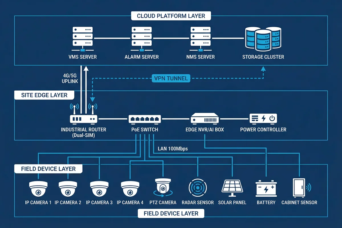
Figure 4.1: Typical three-tier system topology — Cloud Platform Layer (VMS, Alarm, NMS, Storage), Site Edge Layer (Router, PoE Switch, NVR/AI, Power Controller), Field Device Layer (Cameras, Sensors, Solar, Battery), with VPN tunnel and 4G/5G uplink
Cloud Platform Layer
VMS server, alarm server, NMS/monitoring platform, and central storage. Receives selective uplink from all sites. Provides operator access, alarm management, and reporting.
Site Edge Layer
Industrial router (VPN termination, WAN failover), PoE switch (device power + L2 aggregation), edge NVR/AI (local recording + analytics), power controller (load management + telemetry).
Field Device Layer
IP cameras (fixed + PTZ), sensors (radar, PIR, door), solar panel + battery, cabinet environment sensors. All powered and connected through the edge layer.
4.1.1 Backhaul Architecture Options
The choice of backhaul technology is the most consequential architecture decision for unattended sites. The table below compares the four main options across the dimensions that matter most for remote surveillance deployments.
| Backhaul Type | Typical Bandwidth | Latency | Availability | Cost | Best For |
|---|---|---|---|---|---|
| Fiber (leased) | 10–1000 Mbps | 1–5 ms | 99.9%+ | High OPEX | Urban/suburban sites; LPR; high-channel-count |
| 4G/5G Cellular | 5–100 Mbps | 20–80 ms | 95–99% | Medium OPEX | Remote sites; most common choice; dual-SIM for resilience |
| P2P Microwave | 50–300 Mbps | 2–10 ms | 99.5%+ | High CAPEX, low OPEX | Farm/campus with multiple nodes; no cellular coverage |
| Satellite (LEO) | 20–200 Mbps | 20–60 ms | 99%+ | High CAPEX + OPEX | No-coverage wilderness; fire towers; offshore |
Dual-SIM Design Rule: For cellular backhaul, always specify dual-SIM from different carriers. Primary SIM handles all traffic; secondary SIM activates automatically on primary failure. Failover time should be ≤60 seconds. Configure the router to send an alarm when failover occurs so the O&M team can investigate the primary link issue.
4.2 Cabinet Wiring Design
The cabinet wiring diagram defines the physical implementation of the site edge layer. Every connection, wire gauge, fuse rating, and label must be documented in the as-built drawing. The diagram below shows the standard wiring layout for an AC-powered site with battery backup.
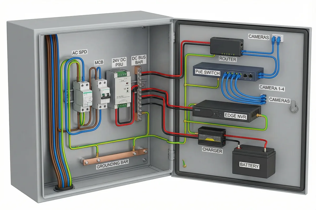
Figure 4.2: Standard cabinet wiring diagram — AC mains input through SPD and MCB to 24V DC power supply, DC bus bar distribution to router, PoE switch, NVR, and battery charger; color-coded wiring with copper grounding bar at base
4.2.1 Wiring Color Code and Standards
| Wire Color | Function | Min. Cross-Section | Notes |
|---|---|---|---|
| Brown | AC Live (L) | 2.5 mm² | IEC 60446; sleeved at all terminations |
| Black or Dark Blue | AC Neutral (N) / DC Negative | 2.5 mm² | Separate colors for AC and DC circuits |
| Green/Yellow | Protective Earth / Bonding | 4–16 mm² | Never use for any other purpose; ring-lug terminations |
| Red | DC Positive (+) | 1.5–4 mm² | Sized to load current; fused at source |
| Blue | Data / PoE (Cat6) | Cat6 STP | Shielded; drain wire bonded to cabinet at one end only |
| Grey | Data (non-PoE patch cables) | Cat6 UTP | Management connections; labeled at both ends |
4.2.2 VLAN Design
All sites must implement VLAN segmentation to isolate camera traffic from management traffic and any OT/process network. The minimum VLAN design for a standard site is shown below.
| VLAN | Devices | Routing Policy | QoS Priority |
|---|---|---|---|
| VLAN 10 (Camera) | All IP cameras, PTZ cameras, NVR (camera-side interface) | Routed to WAN via VPN; no direct internet; no access to VLAN 20/30 | High (DSCP AF41) for video streams; Medium for management traffic |
| VLAN 20 (Management) | Router management, switch management, NVR management interface, power controller | Routed to WAN via VPN; SSH/HTTPS only; MFA enforced at platform | Medium; management traffic should not be starved by video |
| VLAN 30 (OT) | SCADA gateway, process sensors (if integrated) | Isolated; no routing to camera or management VLANs; read-only data export only | High (DSCP EF) for time-critical process data |
| VLAN 99 (Quarantine) | Default VLAN for unassigned ports; new devices before provisioning | No routing; no internet; no access to other VLANs; alarm on any traffic | Lowest; rate-limited |
4.3 Power System Design
The power system is the most critical infrastructure element at unattended sites. The design must address three independent failure modes: mains outage (UPS/battery backup), solar insufficiency (worst-month sizing), and load surge (PoE budget management and staged startup). The power system architecture must be documented in a dedicated wiring diagram separate from the data network diagram.
4.3.1 AC-Powered Site Power Architecture
| Stage | Component | Specification | Design Note |
|---|---|---|---|
| 1. Mains Entry | AC SPD (Type 1+2) | Uc ≥ 275V, Imax ≥ 40kA, remote status indicator | Install at mains entry point; bonding conductor ≤0.5m to grounding bar |
| 2. Protection | MCB (main breaker) | Rated for total load + 25% margin; curve C for inductive loads | Labeled; accessible for emergency shutdown; lockable in OFF position |
| 3. Conversion | DIN-rail DC PSU | 24VDC or 48VDC; efficiency ≥92%; wide input 85–265VAC; output regulation ±1% | Size for total DC load + 30% headroom; redundant PSU for critical sites |
| 4. Backup | Battery + Charger | LiFePO4 preferred; capacity for target autonomy hours at full load; BMS with telemetry | Low-voltage cutoff at 20% SoC; temperature-compensated charging |
| 5. Distribution | DC Bus Bar + Fuses | Copper bus bar; individual fused outputs per load; fuse rating = 1.5× load current | Label each fuse output; spare fuses in cabinet; fuse map in as-built drawing |
| 6. Monitoring | Power Controller / BMS | Voltage, current, SoC telemetry; load shedding relay outputs; SNMP/MQTT reporting | Alarm thresholds: low battery (30% SoC), critical (20% SoC), charger fault |
4.3.2 Solar-Powered Site Power Architecture
Solar-powered sites require additional design elements beyond the AC architecture. The solar charge controller must be sized for the panel array's short-circuit current (Isc) with a 25% safety margin. The battery bank must be sized for the worst-month scenario, which combines the lowest solar irradiance month with the highest load (heaters active in winter). The autonomy calculation must account for at least 3 consecutive overcast days.
| Parameter | Calculation Method | Example (4-camera site) |
|---|---|---|
| Total Site Load | Sum of all device power ratings at worst case (heaters ON, PTZ moving) | 4 cameras × 15W + PTZ 30W + router 15W + switch 20W + NVR 20W + heater 50W = 225W |
| Daily Energy Demand | Total Load (W) × 24h / 1000 | 225W × 24h = 5.4 kWh/day |
| Worst-Month Solar Yield | Panel Wp × Peak Sun Hours (PSH) × efficiency factor (0.75) | 400W × 3.5 PSH × 0.75 = 1.05 kWh/day (insufficient → add panels) |
| Required Panel Power | Daily Energy / (PSH × 0.75) | 5.4 kWh / (3.5 × 0.75) = 2,057W → use 2,200W array |
| Battery Capacity | Daily Energy × Autonomy Days / (DoD × Efficiency) | 5.4 kWh × 3 days / (0.8 × 0.95) = 21.3 kWh → 600Ah @ 48V LiFePO4 |
Critical Warning: Always use worst-month PSH data for the specific site latitude and orientation. Using annual average PSH will result in winter outages. For sites above 40° latitude, winter PSH can be 50–70% lower than summer values. Use PVGIS or NASA SSE data for accurate local irradiance values.