Scenarios & Selection
Chapter 3 · Unattended Surveillance Site Design Guide
This chapter presents eight representative deployment scenarios for unattended surveillance points. Each scenario is characterized by its environmental conditions, threat model, power and backhaul constraints, and the resulting product and configuration selections. The scenarios are not exhaustive but cover the most common site types encountered in practice, and together they illustrate how the design principles from Chapter 2 translate into specific engineering choices.
Wilderness Perimeter Fence Node
Remote nature reserve / mining concession / national park boundary
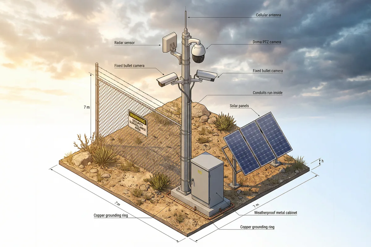
Figure 3.1: Wilderness perimeter fence node — solar-powered pole with PTZ + two fixed cameras, radar sensor, and weatherproof cabinet on copper grounding ring
The wilderness perimeter node is the most demanding scenario in terms of environmental resilience and power autonomy. Sites are typically 5–50 km from the nearest road, with no AC mains power, no fiber, and cellular coverage that may be marginal or absent. Lightning density is often high due to open terrain and elevated pole structures. The primary threats are unauthorized entry, poaching, and equipment theft. A solar + battery system sized for the worst winter month is mandatory, and the pole must be engineered for wind loads up to 40 m/s. The radar sensor provides multi-sensor fusion to reduce false alarms from wildlife movement.
| Parameter | Specification | Notes |
|---|---|---|
| Power Source | Solar 400–800W panels + 200–400Ah LiFePO4 battery | Sized for worst-month irradiance; temp-compensated charging |
| Backhaul | Dual-SIM 4G/5G with directional high-gain antenna (12–18 dBi) | Satellite (Starlink) as fallback for no-coverage zones |
| Cameras | 1× PTZ (30× optical, 200m IR), 2× fixed bullet (4MP, 80m IR, varifocal) | All with heater/defog; radar-triggered PTZ positioning |
| Detection | Millimeter-wave radar (detection range 100m, 120° FoV) + video analytics | Multi-sensor fusion reduces false alarm rate by ≥80% |
| Cabinet | IP66 stainless steel, 600×400×200mm, internal heater + thermostat | Tamper switch + door sensor; padlock + security screws |
| Grounding | Copper ring electrode + 3× vertical rods; ground resistance ≤4Ω; SPD at every cable entry | Lightning rod on pole top; bonding to all metallic elements |
| Pole | Hot-dip galvanized steel, 6–8m, wind load 40m/s, concrete foundation | Internal cable routing; anti-climb collar at 2.5m |
Pipeline Valve Room / Pumping Station
Oil & gas / water utility / chemical pipeline infrastructure
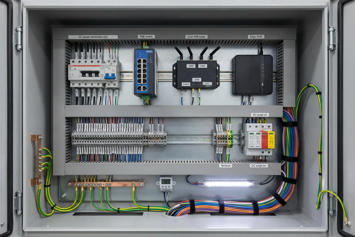
Figure 3.2: Pipeline station cabinet interior — DIN-rail mounted industrial components including PoE switch, dual-SIM router, edge NVR, SPDs, terminal blocks, and copper grounding bar
Pipeline infrastructure nodes combine surveillance with process monitoring. The cabinet interior is the critical design element: all components must be DIN-rail mounted for maintainability, labeled for rapid fault isolation, and protected against the elevated surge risk from long metallic pipeline runs. AC mains power is typically available from the station's own supply, but a UPS with minimum 4-hour backup is required. The primary threats are unauthorized access to valve controls, theft of copper, and process anomaly detection (leak, pressure event). Integration with the SCADA/OT network requires careful VLAN isolation to prevent cross-contamination.
| Parameter | Specification | Notes |
|---|---|---|
| Power Source | AC Mains + 24V DC UPS (≥4h backup); DIN-rail power supply | Low-voltage cutoff to protect battery; load priority outputs |
| Backhaul | Fiber primary (if available) + 4G SIM failover | VPN tunnel mandatory; OT VLAN isolated from camera VLAN |
| Cameras | 2–4× fixed dome (2MP, 30m IR, wide-angle for room coverage) + 1× PTZ for exterior gate | ONVIF Profile S+G; privacy masking for process displays |
| Cabinet | IP54 indoor steel cabinet, DIN-rail mounting, 19" rack option for larger sites | All components labeled; cable management trunking; spare fuse kit |
| Surge Protection | AC SPD (Type 1+2) at mains entry; DC SPD on all camera and data lines; Ethernet SPD on all external ports | Pipeline runs create long surge paths; SPD coordination essential |
| Integration | Modbus/OPC-UA gateway for process data overlay; alarm correlation with SCADA events | Read-only integration; no write access from camera network to OT |
Solar / Wind Farm Perimeter Node
Renewable energy generation site — large-area perimeter with inverter station coverage
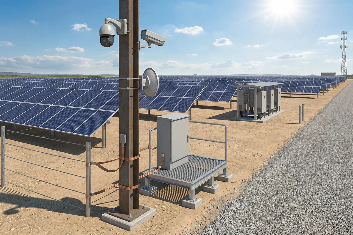
Figure 3.3: Solar farm perimeter node — pole-mounted PTZ and fixed camera with microwave backhaul dish, weatherproof cabinet on raised stand, copper bonding strap to pole base
Solar and wind farms present a unique combination of abundant on-site power generation (from the farm's own AC supply) and large perimeter areas requiring multiple distributed nodes. The key challenge is backhaul: fiber is often not run to perimeter nodes, and cellular coverage may be poor in rural flat terrain. Point-to-point microwave or licensed radio links between perimeter nodes and a central aggregation point are the preferred solution. Flooding risk must be assessed for cabinet placement, and the dense metallic structure of solar panel frames creates complex grounding requirements. Panel theft and inverter tampering are the primary threats.
| Parameter | Specification | Notes |
|---|---|---|
| Power Source | AC Farm Supply (230V/400V) + local UPS (2h backup) | Separate MCB for surveillance load; surge protection at feed point |
| Backhaul | P2P Microwave (licensed, 100–300 Mbps) between perimeter nodes and central hub | Cellular as backup; GPS sync for timing; alignment critical |
| Cameras | 1× long-range PTZ (30×, 500m IR, laser illuminator option) + 1–2× fixed wide-angle for local coverage | Thermal option for night perimeter patrol; AI perimeter analytics |
| Grounding | Bonding to solar frame grounding network; dedicated SPD for microwave dish; equipotential bonding ring at cabinet base | Solar frames create complex ground paths; consult structural engineer |
| Cabinet Placement | Raised steel stand (min. 300mm above flood level); concrete anchor bolts; anti-tilt design | Flood risk assessment required; drainage channel around base |
Telecom Tower / Base Station Fence Camera
Mobile network tower site — compact anti-vandal installation with minimal footprint
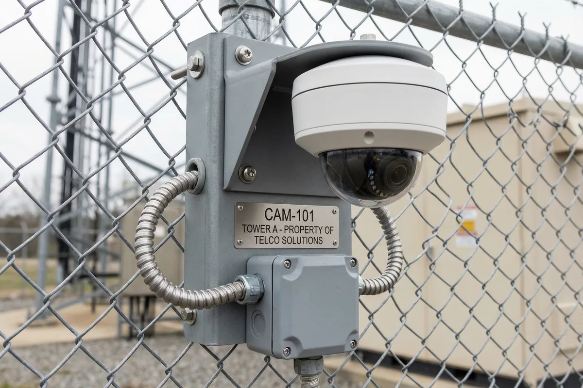
Figure 3.4: Telecom tower fence camera — vandal-resistant dome on anti-climb bracket with stainless steel label plate, external conduit with drip loop, and weatherproof junction box
Telecom tower sites are characterized by excellent backhaul availability (the tower's own fiber or microwave link can be leveraged), reliable AC power from the tower's rectifier system, but extremely high vandalism and theft risk. The camera installation must be anti-vandal (IK10 minimum), tamper-evident, and use anti-climb brackets to prevent camera repositioning. The tower operator's network can often provide a VLAN for surveillance traffic, eliminating the need for a separate cellular SIM. Grounding is typically excellent due to the tower's own earthing system, but bonding of the camera bracket to the tower ground must be verified.
| Parameter | Specification | Notes |
|---|---|---|
| Camera Type | IK10 vandal-resistant dome, 4MP, 30m IR, wide-angle (2.8mm fixed or 2.8–12mm varifocal) | Anti-tamper screws; tamper switch output wired to alarm input |
| Bracket | Anti-climb steel bracket, welded to fence post or tower leg; stainless steel fasteners throughout | Bracket bonded to tower grounding system with 16mm² green/yellow conductor |
| Power | Tower Rectifier 48V DC or 230V AC from tower PDU; PoE injector in shelter | Coordinate with tower operator for load allocation; fused spur |
| Backhaul | Tower fiber or microwave VLAN; coordinate VLAN ID and bandwidth allocation with operator | Backup SIM in shelter router if tower link is shared/unreliable |
| Conduit | Liquid-tight flexible conduit with drip loop at camera entry; rigid conduit on fence post | Drip loop prevents water ingress; conduit bonded to bracket |
Forest Fire Lookout Tower
Elevated hilltop tower — long-range thermal + PTZ for early fire detection
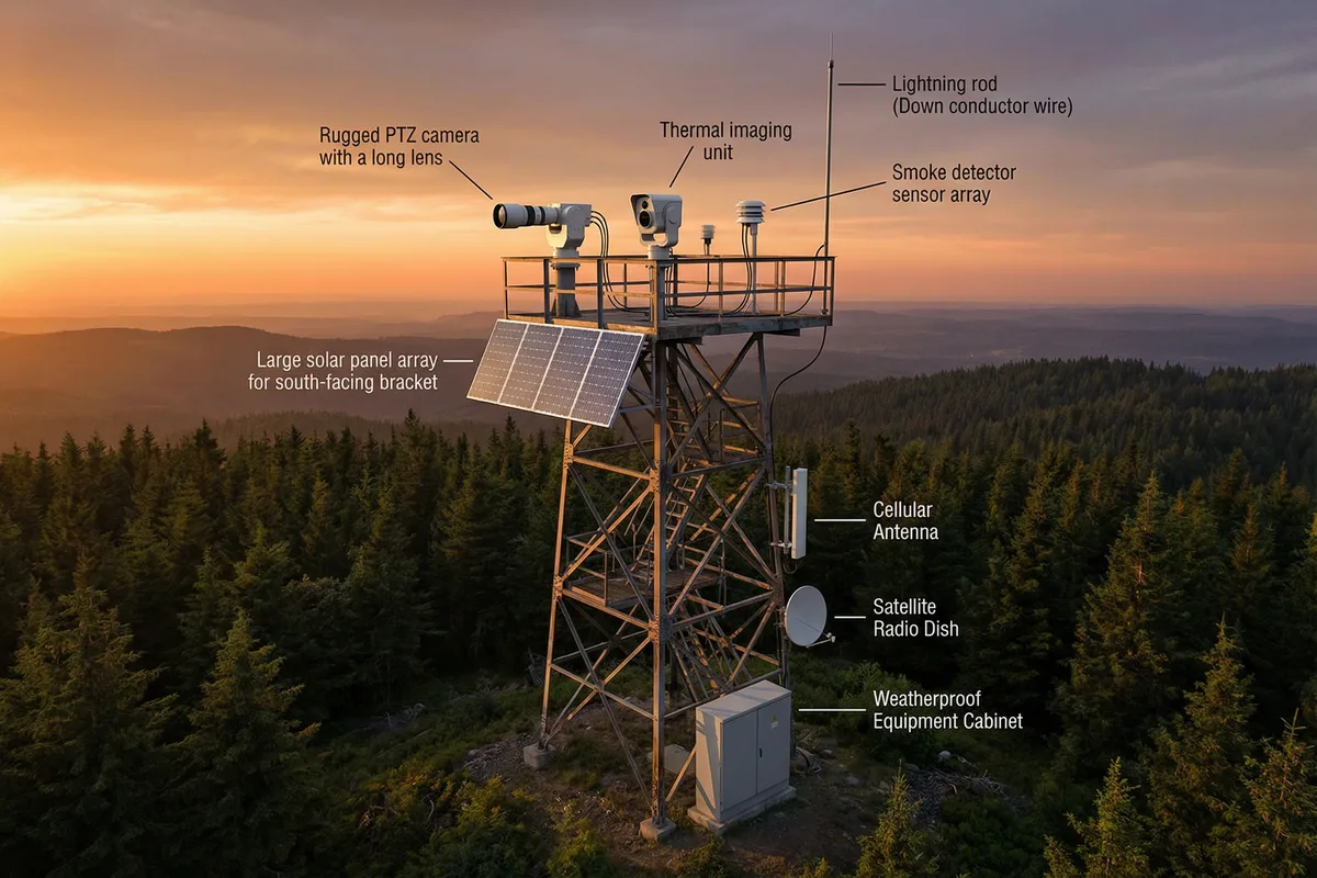
Figure 3.5: Forest fire lookout tower — 20m lattice tower with long-range PTZ, thermal camera, smoke detector array, solar panels, satellite dish, cellular antenna, and weatherproof cabinet at base
Forest fire lookout towers represent the highest-performance end of the unattended surveillance spectrum. The primary mission is early fire detection at ranges of 5–20 km using thermal imaging and smoke analytics, combined with PTZ optical zoom for confirmation and documentation. Tower height (15–25m) maximizes detection range but creates extreme wind loads and lightning exposure. Solar power with large battery banks is standard. Satellite backhaul (Starlink or VSAT) is often required due to the remote hilltop location. The thermal camera's sensitivity to temperature differential enables detection of sub-hectare fires before visible smoke appears.
| Parameter | Specification | Notes |
|---|---|---|
| Thermal Camera | Uncooled LWIR, 640×512 or 1280×1024 detector, 25mm–75mm lens, NETD ≤50mK | Continuous 360° pan-scan with fire hotspot analytics; GPS-tagged alarm coordinates |
| PTZ Camera | 30–40× optical zoom, 2km IR illuminator, laser rangefinder option; heater/defog mandatory | Alarm-triggered positioning to thermal hotspot coordinates |
| Power | Solar 800W–2kW + 400–800Ah LiFePO4; wind turbine supplement in high-wind sites | Worst-month sizing critical; redundant charge controllers |
| Backhaul | Satellite (Starlink/VSAT) primary; cellular 4G backup if available | Low-latency satellite preferred for alarm responsiveness |
| Tower | Lattice steel, 15–25m, hot-dip galvanized, wind load 50m/s; structural engineering required | Separate lightning protection system per IEC 62305; down conductors on all legs |
Rural Traffic Checkpoint / Road Monitoring
Highway / rural road — license plate recognition and traffic overview
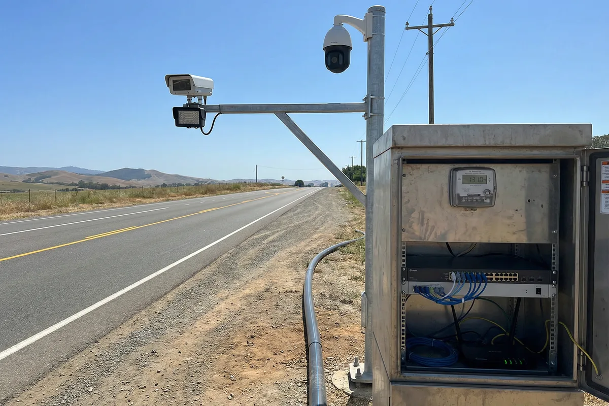
Figure 3.6: Rural traffic checkpoint — cantilever arm with LPR camera and IR illuminator, PTZ overview camera, roadside cabinet with power meter, PoE switch, and router with fiber conduit
Rural traffic checkpoints combine license plate recognition (LPR) with general traffic overview. The LPR camera requires precise positioning and illumination design: the IR illuminator must be co-axial with the camera axis, the camera must be aimed at the vehicle front plate at the correct angle (15–25° from horizontal), and the trigger zone must be defined to capture plates at the correct distance for the chosen focal length. AC mains power is typically available from roadside supply, but surge protection is critical due to long overhead cable runs. Fiber is the preferred backhaul for LPR due to the high data volume of plate images.
| Parameter | Specification | Notes |
|---|---|---|
| LPR Camera | 2–4MP, 1/1.8" sensor, global shutter, 850nm IR illuminator (co-axial), 8–50mm motorized zoom | Shutter speed ≥1/1000s for 120km/h; WDR ≥120dB for headlight compensation |
| Overview Camera | PTZ or fixed wide-angle, 4MP, covering both lanes and roadside for incident documentation | Separate from LPR; provides context for plate-matched events |
| Mounting | Cantilever arm, 3–5m height, 1–3m overhang; galvanized steel; road authority approval required | Arm must clear max vehicle height (4.5m); wind load calculation required |
| Power | AC Mains from roadside supply; Type 1+2 SPD at mains entry; UPS (1h backup) | Coordinate with road authority for power supply; metered supply preferred |
| Backhaul | Fiber preferred (LPR data volume); 4G backup for alarms only | Fiber conduit in road verge; coordination with road authority required |
Warehouse / Industrial Perimeter
Logistics warehouse / industrial estate — building-mounted corner cameras with IR floodlight
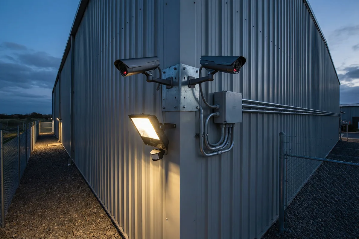
Figure 3.7: Warehouse perimeter — corner-mounted dual bullet cameras with PIR-triggered IR floodlight, weatherproof junction box, and conduit along building fascia at dusk showing IR illumination effect
Warehouse and industrial perimeter surveillance benefits from AC mains power and often fiber or structured cabling within the building, but the outdoor environment presents challenges including large open areas requiring long-range coverage, high-value targets attracting organized theft, and the need for evidence-grade video for insurance and legal purposes. Corner mounting with two cameras provides 180° coverage of both wall faces from a single installation point. The PIR-triggered IR floodlight provides supplementary illumination for evidence-grade color video at night without the cost of continuous lighting. Integration with the building management system (BMS) and access control is common.
| Parameter | Specification | Notes |
|---|---|---|
| Cameras | 2× 4–8MP bullet cameras per corner, varifocal 2.8–12mm, 50m IR, IP67, IK10 | One camera per wall face; FoV overlap at corner for no blind spot |
| Illumination | PIR-triggered IR floodlight (850nm, 50m range) + white light option for color evidence | PIR zone aligned with camera FoV; adjustable sensitivity and hold time |
| Recording | NVR with 30-day retention at 4MP/15fps; RAID-1 for evidence integrity; SMART monitoring | Evidence export with chain-of-custody metadata; watermarking option |
| Integration | Alarm output to BMS; access control event correlation; optional LPR at gate | Read-only integration with BMS; separate network segment for cameras |
| Power | AC Mains from building distribution board; UPS (4h backup) for NVR and router | Dedicated circuit for surveillance; MCB labeled and locked |
Temporary Construction Site
Active construction site — portable solar mast with rapid deployment and relocation
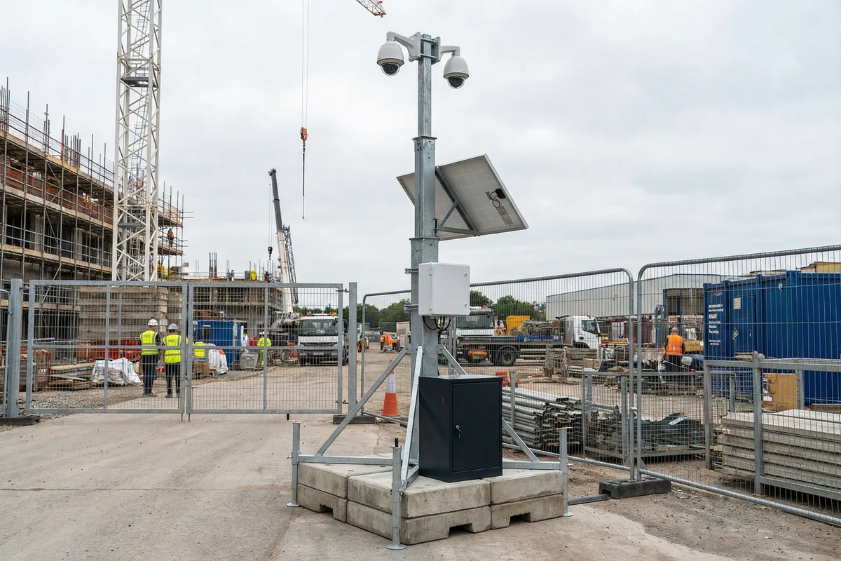
Figure 3.8: Construction site portable mast — ballast-base steel mast with two cameras, cellular router enclosure, solar panel, and lockable battery cabinet at base; construction site background with cranes and workers
Construction site surveillance must balance security effectiveness with the need for rapid deployment, relocation as the site evolves, and eventual removal. The portable mast with ballast base (no ground anchoring) enables repositioning within hours. Solar + battery power eliminates the need for generator or temporary mains connection. Cellular backhaul provides immediate connectivity. The primary threats are material theft (copper, tools, equipment), unauthorized access outside working hours, and health & safety compliance monitoring. The system must be designed for easy handover between site phases and eventual decommissioning with full data export.
| Parameter | Specification | Notes |
|---|---|---|
| Mast | Portable steel mast 5–6m, ballast base (4× concrete blocks, 500kg total), anti-tilt safety chain | Forklift pockets in base for repositioning; wind limit 25m/s for portable type |
| Power | Solar 200–400W + 100–200Ah LiFePO4 in lockable base cabinet; 48h autonomy target | Low-voltage cutoff mandatory; battery in lockable anti-theft cabinet |
| Cameras | 2× 4MP bullet cameras, 30m IR, wide-angle; optional PTZ for large sites | Cameras on quick-release brackets for rapid removal; cable coiled inside mast |
| Backhaul | 4G SIM router in weatherproof enclosure on mast; pre-configured for plug-and-play | SIM pre-activated; VPN auto-connects on power-up; no on-site configuration needed |
| Decommissioning | Full data export before removal; configuration backup to cloud; SIM deactivation procedure | Data retention policy must be defined before deployment; export evidence before teardown |
3.9 Scenario Selection Matrix
The following matrix summarizes the key characteristics of all eight scenarios to assist in rapid scenario identification and solution selection. Use this matrix to match a new site's characteristics to the most relevant scenario, then adapt the detailed specifications from that scenario's section.
| Scenario | AC Power | Solar | Fiber | Cellular | Satellite | Thermal | LPR | Portable | Lightning Risk |
|---|---|---|---|---|---|---|---|---|---|
| 1. Wilderness Fence | ✗ | ✓ | ✗ | ▲ | ▲ | ▲ | ✗ | ✗ | High |
| 2. Pipeline Station | ✓ | ✗ | ▲ | ▲ | ✗ | ✗ | ✗ | ✗ | High |
| 3. Solar/Wind Farm | ✓ | ✗ | ✗ | ▲ | ✗ | ▲ | ✗ | ✗ | High |
| 4. Telecom Tower | ✓ | ✗ | ✓ | ✓ | ✗ | ✗ | ✗ | ✗ | Very High |
| 5. Forest Fire Tower | ✗ | ✓ | ✗ | ▲ | ✓ | ✓ | ✗ | ✗ | Very High |
| 6. Traffic Checkpoint | ✓ | ✗ | ✓ | ▲ | ✗ | ✗ | ✓ | ✗ | Medium |
| 7. Warehouse Perimeter | ✓ | ✗ | ✓ | ▲ | ✗ | ✗ | ▲ | ✗ | Low |
| 8. Construction Site | ✗ | ✓ | ✗ | ✓ | ✗ | ✗ | ✗ | ✓ | Low |
✓ = Standard/Primary | ▲ = Optional/Backup | ✗ = Not applicable