Security & Risks
Chapter 6 · Unattended Surveillance Site Design Guide
Unattended surveillance sites face a unique combination of physical, electrical, environmental, and cyber threats that are absent or less severe in attended installations. Because no personnel are on-site to respond to incidents, the system must be designed to withstand threats autonomously, detect and report failures in real time, and degrade gracefully rather than fail catastrophically. This chapter provides a structured risk assessment framework and mitigation strategies for each major threat category.
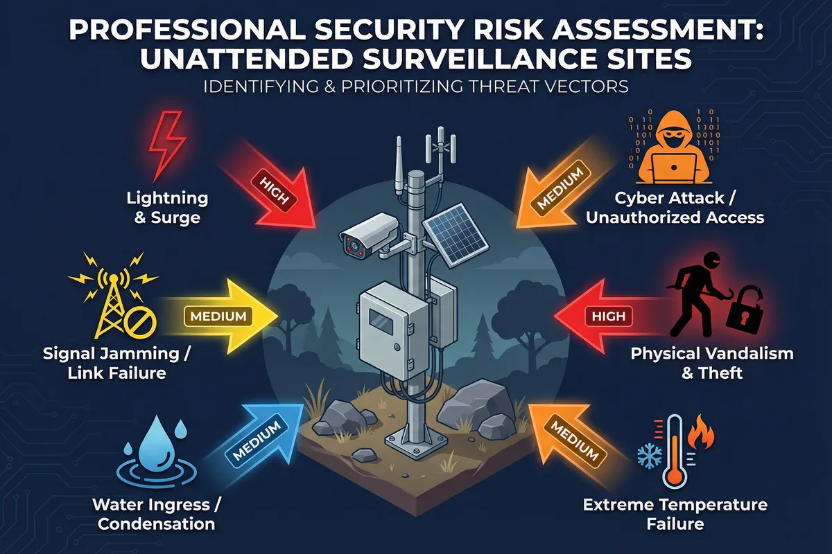
Figure 6.1: Security risk assessment for unattended surveillance sites — six primary threat vectors: Lightning & Surge (HIGH), Physical Vandalism & Theft (HIGH), Cyber Attack (MEDIUM), Signal Jamming (MEDIUM), Water Ingress (MEDIUM), Extreme Temperature Failure (MEDIUM)
6.1 Risk Assessment Matrix
The risk matrix below evaluates each threat category by likelihood, impact severity, and the primary mitigation measures. The risk level is the product of likelihood and impact, and determines the priority of mitigation investment.
| Threat Category | Likelihood | Impact | Risk Level | Primary Mitigation |
|---|---|---|---|---|
| Lightning & Electrical Surge | High (remote sites) | Catastrophic (total loss) | HIGH | Lightning rod, SPD at every cable entry, ground resistance ≤4Ω, equipotential bonding |
| Physical Vandalism & Theft | High (unattended) | Major (equipment loss, data gap) | HIGH | IK10 enclosures, anti-climb brackets, tamper switches, security screws, anti-theft cable anchors |
| Cyber Attack / Unauthorized Access | Medium | Major (data breach, system compromise) | MEDIUM | VPN tunnel, VLAN segmentation, MFA, firmware patching, default credential elimination |
| Signal Jamming / Link Failure | Medium | Moderate (monitoring gap) | MEDIUM | Dual-SIM failover, local recording buffer, alarm on link loss, anti-jam antenna placement |
| Water Ingress / Condensation | Medium | Major (equipment damage) | MEDIUM | IP66+ enclosures, cable glands, drip loops, silica gel desiccant, cabinet heater with thermostat |
| Extreme Temperature Failure | Medium (climate-dependent) | Moderate (performance degradation) | MEDIUM | Wide-temp components (-40°C to +70°C), cabinet heater (cold), ventilation/fan (hot), thermal monitoring |
| Power Failure / Battery Depletion | Medium | Major (complete outage) | MEDIUM | UPS/battery backup, solar worst-month sizing, low-battery alarm, load shedding priority |
| Storage Failure (HDD/SSD) | Low–Medium | Moderate (evidence loss) | LOW–MEDIUM | Surveillance-rated drives, SMART monitoring with alerting, RAID-1 for critical sites, cloud backup |
6.2 Lightning & Surge Protection
Lightning is the leading cause of total site loss at remote unattended surveillance installations. A single direct or nearby lightning strike can destroy every electronic component in the cabinet if the protection system is inadequate. The protection strategy must address three distinct threat paths: direct strike to the pole or structure, conducted surge on power cables, and conducted surge on data cables.
6.2.1 Protection Hierarchy
| Protection Level | Component | Specification | Location |
|---|---|---|---|
| Level 1: Air Terminal | Lightning rod (Franklin rod or ESE) | Copper or stainless steel; 1m above highest point; protection angle 45–60° | Pole top, above all antennas and cameras |
| Level 2: Down Conductor | Copper conductor ≥16mm² | Shortest path to ground; no sharp bends; secured every 1m; no joints | Pole exterior, separate from data/power cables |
| Level 3: Earth Termination | Ground ring + vertical rods | Copper ring electrode + 3× 1.5m vertical rods; resistance ≤4Ω (≤2Ω for high-risk sites) | Around pole base; minimum 1m from foundation |
| Level 4: Equipotential Bonding | Copper bonding conductors ≥6mm² | All metallic elements bonded to cabinet grounding bar; single reference ground point | Cabinet interior; all cable shields; pole metalwork |
| Level 5: AC SPD | Type 1+2 combined SPD | Uc ≥275V, Iimp ≥12.5kA (Type 1), Imax ≥40kA (Type 2); remote fault indicator | AC mains entry to cabinet; bonding conductor ≤0.5m to ground bar |
| Level 6: DC SPD | 2-pole DC SPD | Uc ≥ 1.2× Voc of solar array; Imax ≥20kA; DIN-rail mount | Solar charge controller input; between panels and controller |
| Level 7: Data SPD | Ethernet SPD (RJ45) | Cat6/PoE++; 10kA discharge; 1Gbps; DIN-rail; in-line transparent operation | Every external Ethernet port; camera cable entries to cabinet |
Critical Failure Mode: The most common lightning protection failure is inadequate bonding — the SPDs are installed but the ground resistance is too high (>10Ω) or the bonding conductors are too long (>0.5m between SPD and ground bar). In this case, the SPD cannot discharge the surge energy fast enough, and the residual voltage exceeds the equipment's withstand voltage. Always measure ground resistance after installation and before energizing the system.
6.3 Cybersecurity for Unattended Sites
Unattended surveillance sites are increasingly targeted by cyber attacks because they combine internet connectivity (cellular/fiber backhaul) with physical inaccessibility that delays detection of compromise. The attack surface includes the router's WAN interface, the VPN endpoint, the camera web interfaces, the NVR management interface, and any cloud platform APIs. A layered defense strategy is required.
6.3.1 Minimum Cybersecurity Baseline
- Eliminate all default credentials: Change all factory default usernames and passwords before deployment. Use a password manager to generate and store unique strong passwords for each device and site.
- VPN-only remote access: No device should be directly accessible from the internet. All remote access must traverse the VPN tunnel. Disable any UPnP, port forwarding, or P2P cloud access features that bypass the VPN.
- Firmware currency: Establish a quarterly firmware review and update cycle. Subscribe to vendor security advisories. Critical CVEs must be patched within 30 days of disclosure.
- VLAN segmentation: Implement the four-VLAN design from Chapter 4. Camera traffic must never be on the same VLAN as management traffic.
- Disable unused services: Disable Telnet, HTTP (use HTTPS only), UPnP, ONVIF discovery (on WAN-facing interfaces), and any other services not required for operation.
- Log retention and alerting: Configure syslog forwarding to the central NMS. Alert on: failed login attempts (>3 in 5 minutes), new device on camera VLAN, VPN tunnel failure, configuration changes.
| Attack Vector | Mitigation | Detection Method |
|---|---|---|
| Brute-force login to camera/NVR | Account lockout after 5 attempts; strong passwords; disable HTTP | Failed login alert in NMS; syslog monitoring |
| VPN endpoint exploitation | Keep VPN firmware current; use certificate-based auth; restrict source IPs | VPN connection log anomaly detection |
| Man-in-the-middle on cellular link | TLS 1.3 for all management; certificate pinning; VPN encryption | Certificate mismatch alerts |
| Physical access to router/switch | Cabinet lock; tamper switch; console port disabled; boot password | Cabinet door sensor alarm; tamper switch alarm |
| Rogue device on camera VLAN | 802.1X port authentication; MAC address allowlist on switch | New MAC address alert on camera VLAN |
6.4 Physical Security Measures
Physical security at unattended sites must deter, delay, and detect unauthorized access to the equipment. The goal is not to make the equipment impenetrable — a determined attacker with tools will always be able to remove equipment — but to ensure that any tampering is detected and reported before the attacker can exploit the compromised system, and to make opportunistic theft unattractive through visible deterrents.
| Element | Specification | Purpose |
|---|---|---|
| Cabinet Lock | Stainless steel padlock (≥6mm shackle) + security hasp; or cylinder lock with restricted key | Deter opportunistic access; delay forced entry |
| Security Screws | Torx Plus, one-way, or spanner-head screws for all external camera and bracket fasteners | Prevent camera repositioning or removal without special tools |
| Anti-Climb Collar | Stainless steel anti-climb collar at 2.5m height on pole; smooth surface, no footholds below | Prevent unauthorized pole climbing to access cameras or antennas |
| Tamper Switch | Magnetic or microswitch on cabinet door; wired to NVR/router alarm input; generates immediate alert | Detect cabinet opening; trigger alarm and video recording |
| Cable Anchoring | Steel cable anchor (aircraft cable, 6mm, with padlock) on each camera and cabinet; anchored to pole or structure | Prevent equipment removal even if security screws are defeated |
| Asset Labeling | Stainless steel engraved label with asset ID, owner contact, and "CCTV MONITORED" warning; UV-resistant | Deter theft; aid recovery; legal evidence of ownership |
| Warning Signage | Weatherproof sign at 1.5m height: "CCTV IN OPERATION — TRESPASSERS WILL BE PROSECUTED" | Legal compliance; deterrence; reduce liability |
Self-Protection Design Principle: The surveillance system must monitor itself. A camera pointed at the cabinet door, a tamper switch on the cabinet, and a door sensor on any access gate are essential. If the system can only monitor the perimeter but not its own equipment, an attacker can disable the system before anyone is alerted. Configure the NVR to trigger an alarm and upload a snapshot to the cloud when the cabinet tamper switch activates.