Support & Integration
Chapter 7 · Unattended Surveillance Site Design Guide
The supporting systems and integration requirements for unattended surveillance sites are as important as the core camera and recording equipment. A site that has excellent cameras but inadequate power, grounding, backhaul, or environmental protection will fail prematurely. This chapter covers all supporting systems — power, communications, grounding, environmental control, and third-party integration — as an integrated whole rather than as individual components.
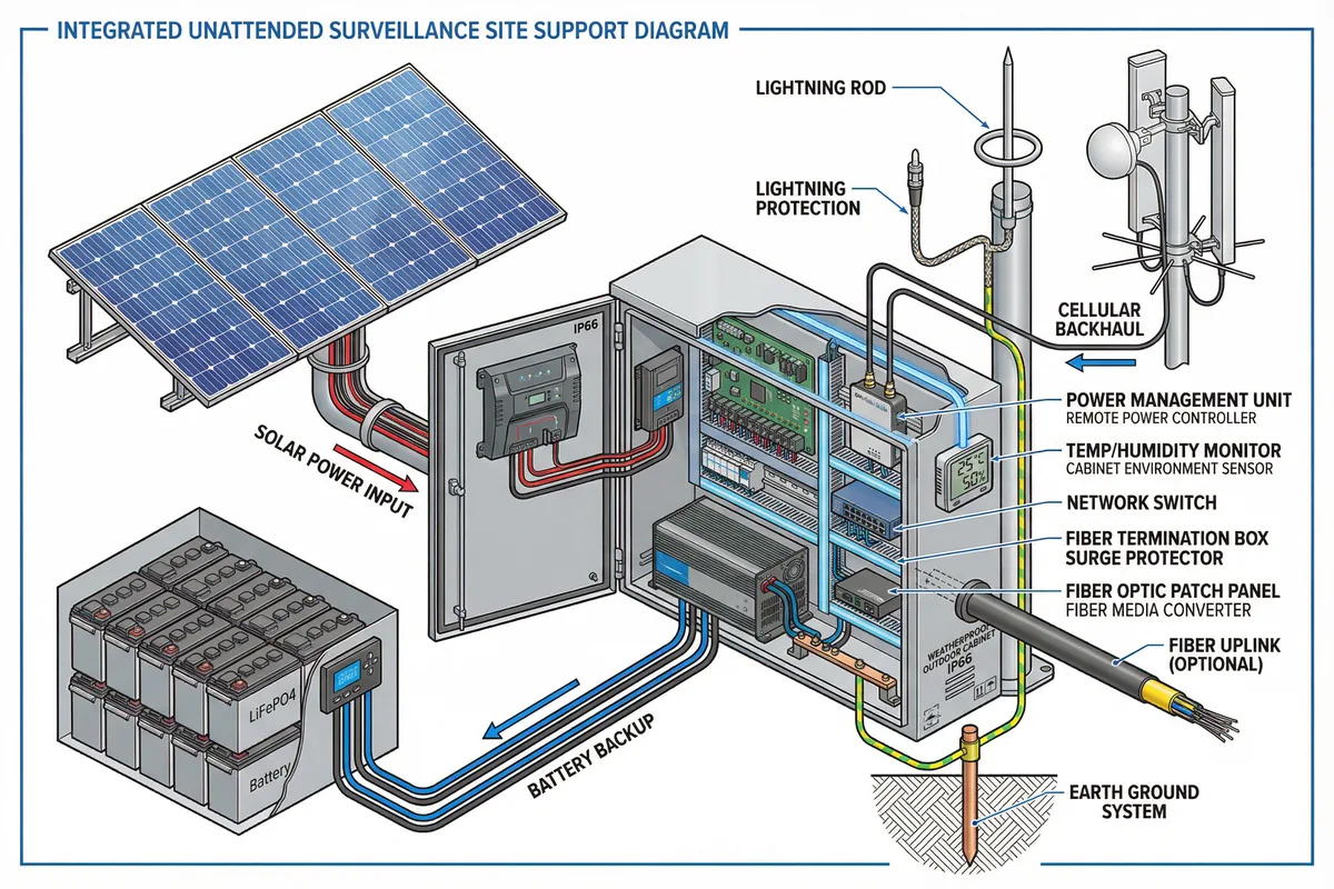
Figure 7.1: Integrated support equipment diagram — all supporting systems shown as a unified assembly: solar panel array, LiFePO4 battery bank, IP66 outdoor cabinet with power management and environmental monitoring, cellular backhaul antenna, lightning protection system, fiber uplink, and earth ground system with vertical rod electrode
7.1 Power Support Systems
The power support system encompasses all components beyond the core surveillance devices that are required to deliver reliable, conditioned power to the site. This includes the solar charge controller, battery management system, DC power distribution, UPS module, and the power monitoring and control interface.
Solar Charge Controller
MPPT type (not PWM) for efficiency ≥98%; rated for panel array Isc × 1.25; temperature-compensated charging; battery type selection (LiFePO4/AGM); remote telemetry via RS-485/MQTT; DIN-rail mount.
Battery Management System (BMS)
Integrated in LiFePO4 battery pack; cell balancing; over-charge, over-discharge, over-temperature protection; SoC reporting via RS-485 or CAN; low-voltage cutoff at 20% SoC; high-temperature cutoff at 55°C.
DC Power Distribution
Copper bus bar; individual fused outputs per load; fuse rating = 1.5× load current; spare fuses in cabinet; fuse map in as-built drawing; DIN-rail mounted; all outputs labeled with load ID and fuse rating.
Power Monitoring Controller
Measures: battery voltage, current, SoC, temperature; solar input power; load power per circuit; AC mains status (if applicable); reports via SNMP/MQTT to NMS; configurable alarm thresholds; load shedding relay outputs.
7.2 Communications Support Systems
The communications support systems include all infrastructure required to establish and maintain the backhaul link, beyond the router itself. This includes antenna systems, cable management, and link monitoring.
| Component | Specification | Installation Notes |
|---|---|---|
| Cellular Antenna (Outdoor) | Directional (12–18 dBi) or omnidirectional (5–9 dBi); LTE Band-compatible; N-type connector; UV-stabilized radome; IP67; -40°C to +70°C | Mount above cabinet top; coaxial cable ≤10m (use LMR-400 for longer runs); lightning arrestor at cable entry; drip loop at antenna base |
| Coaxial Cable (Cellular) | LMR-400 or equivalent; loss ≤0.3 dB/m at 2.4GHz; weatherproof connectors; UV-resistant jacket | Secure every 300mm; avoid sharp bends (min. bend radius 50mm); seal all connectors with self-amalgamating tape; label both ends |
| GPS Antenna (NTP Sync) | Active GPS antenna; 3–5V supply; SMA connector; clear sky view required; mount on pole top away from cellular antenna | GPS provides accurate time sync for all site devices; critical for alarm timestamp accuracy and forensic evidence integrity |
| Fiber Termination Box | IP65 outdoor fiber termination box; SC/LC adapters; splice tray; cable strain relief; UV-resistant | Mount at pole base or cabinet exterior; fiber cable enters from below with drip loop; armored fiber cable preferred for outdoor runs |
| Microwave Dish (P2P) | Licensed or unlicensed band; alignment accuracy ≤0.1°; wind load rated; integrated PoE power; alignment LED indicator | Professional alignment required; document azimuth and elevation angles in as-built; re-check alignment after any pole movement or high-wind event |
7.3 Environmental Control & Monitoring
Cabinet environmental control prevents condensation, overheating, and freezing — the three most common environmental failure modes. The control system must be automatic (thermostat-controlled) and must report its status to the central NMS so that failures are detected before they cause equipment damage.
| Condition | Threshold | Control Response | Monitoring Alarm |
|---|---|---|---|
| Low Temperature | Cabinet temp < +5°C | Cabinet heater activates (thermostat-controlled, 30–100W) | Alarm if heater fails to raise temp within 30 min |
| High Temperature | Cabinet temp > +45°C | Ventilation fan activates; load shedding if temp continues to rise | Alarm at +50°C; critical alarm at +60°C |
| High Humidity | Relative humidity > 85% | Silica gel desiccant (passive); heater activation to reduce RH | Alarm if RH >90% for >1 hour |
| Water Ingress | Water sensor in cabinet base | No automatic response; requires immediate O&M dispatch | Immediate critical alarm; escalate to on-call engineer |
| Cabinet Door Open | Tamper switch activated | Trigger video recording; send snapshot to cloud | Immediate alarm; log timestamp and duration |
7.4 Third-Party System Integration
Unattended surveillance sites are frequently required to integrate with third-party systems including SCADA/OT platforms, access control systems, building management systems (BMS), and emergency response dispatch systems. All integrations must be designed with strict security boundaries and read-only data flows where possible.
| Integration Type | Protocol / Interface | Data Direction | Security Requirement |
|---|---|---|---|
| SCADA / OT Platform | Modbus TCP (read-only), OPC-UA, MQTT | OT → Surveillance (event trigger only); no write access from surveillance to OT | Dedicated VLAN 30; hardware data diode for critical OT; no IP routing between VLANs |
| Access Control System | Wiegand, OSDP, or TCP/IP API | Bidirectional: access events trigger camera recording; camera analytics can trigger door lock | Encrypted API; certificate authentication; audit log of all commands |
| Building Management System | BACnet/IP, Modbus, REST API | BMS → Surveillance (alarm events); Surveillance → BMS (camera status, alarm confirmation) | Read-only preferred; write access requires explicit approval and audit trail |
| Emergency Dispatch | SMTP (email), SMS gateway, webhook, SIP (VoIP) | Surveillance → Dispatch (alarm notifications, snapshots, GPS coordinates) | TLS-encrypted; authenticated sender; rate limiting to prevent alarm flooding |
| GIS / Mapping Platform | REST API, GeoJSON, MQTT | Surveillance → GIS (camera position, status, alarm location) | API key authentication; HTTPS only; no sensitive video data in GIS feed |
Integration Design Principle: Every integration point is a potential security vulnerability and a potential failure point. Before implementing any integration, document the data flow, the security controls at each end, the failure mode (what happens if the integration link fails), and the test procedure. Integrations should be tested in isolation before being connected to the live surveillance system.