Quality & Acceptance
Chapter 10 · Unattended Surveillance Site Design Guide
Quality acceptance for unattended surveillance sites is a critical gate that determines whether a site is ready for handover and long-term autonomous operation. Unlike attended installations where operational issues can be quickly identified and corrected by on-site personnel, unattended sites must meet a higher standard of quality at handover because any deficiency will persist until the next scheduled maintenance visit. This chapter defines the acceptance criteria, testing procedures, and documentation requirements for a professional site handover.
10.1 Quality Standards: Pass vs. Fail Comparison
The comparison below illustrates the visual and technical difference between a substandard installation that would fail acceptance and a professional installation that meets all quality criteria. Every element visible in the comparison — cable management, weatherproofing, camera aim, and image quality — is a measurable acceptance criterion.
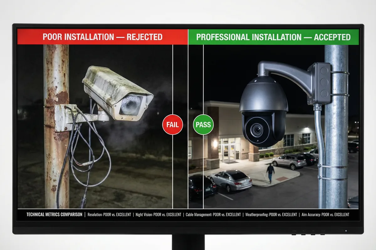
Figure 10.1: Quality comparison — Poor installation (FAIL): rusty pole, condensation on lens, loose cables, wrong aim angle vs. Professional installation (PASS): clean galvanized pole, properly aimed camera, neatly routed cables in conduit, weatherproof cable glands, correct IR illumination
10.2 Acceptance Criteria by Category
The acceptance criteria are organized into seven categories. Each criterion has a defined pass/fail threshold. All criteria in the "Critical" column must pass before the site can be accepted. "Major" criteria failures require remediation within 30 days. "Minor" criteria failures are noted in the punch list and must be addressed before the warranty period begins.
| Category | Criterion | Pass Threshold | Severity |
|---|---|---|---|
| Image Quality | Daytime image clarity | No blur, no lens contamination, correct focus at target distance | Critical |
| Night vision / IR performance | Identifiable image at rated IR distance; no IR bloom on nearby objects | Critical | |
| Camera aim accuracy | Target area fully within FOV; no more than 10% of FOV wasted on sky or ground | Critical | |
| Pixel density at target | ≥62 px/m for detection; ≥125 px/m for recognition; ≥250 px/m for identification | Critical | |
| Mechanical | Camera bracket torque | All fasteners torqued to specification; no movement when force applied by hand | Critical |
| Cable management | All cables in conduit or cable tray; no exposed cable runs >300mm; no sharp bends | Critical | |
| Weatherproofing | All cable entries sealed with cable glands; drip loops present on all outdoor cables; no open conduit ends | Critical | |
| Electrical | Ground resistance | ≤4Ω measured with 3-terminal method; ≤2Ω for high-risk sites | Critical |
| SPD installation | SPD installed at all cable entries; bonding conductor ≤0.5m; SPD fault indicator green | Critical | |
| Power quality | DC supply voltage within ±5% of rated; no ripple >100mV; all fuses correctly rated | Major | |
| Network | Network connectivity | All cameras reachable from NVR; NVR reachable from control center; VPN established | Critical |
| Bandwidth verification | Uplink bandwidth ≥ calculated requirement + 20% margin; measured with speed test | Major | |
| VLAN segmentation | Camera VLAN cannot reach management VLAN; verified with ping test across VLANs | Major | |
| Recording | Recording continuity | 24-hour recording test: no gaps >30 seconds; all cameras recording at specified resolution | Critical |
| Storage capacity | Available storage ≥ calculated requirement; SMART status healthy; write speed verified | Major | |
| Alarm & Notification | Motion detection | Motion alarm triggers within 2 seconds; snapshot uploaded to cloud within 30 seconds | Major |
| Tamper alarm | Cabinet tamper switch triggers alarm within 5 seconds; NMS receives alarm notification | Major | |
| Documentation | As-built drawings | Cable routing plan, equipment schedule, and network diagram updated to reflect actual installation | Major |
| Test records | Ground resistance test, cable test, and bandwidth test results documented with date and tester name | Major |
10.3 Acceptance Test Procedure
The acceptance test must be conducted in a defined sequence. Tests that depend on previous results (e.g., recording tests depend on network connectivity) must not be performed until the prerequisite tests have passed. The test sequence is designed to identify failures at the earliest possible stage to minimize wasted testing time.
| Step | Test | Method | Pass Criterion | Tool Required |
|---|---|---|---|---|
| 1 | Visual Inspection | Walk-through inspection of all mechanical and weatherproofing elements | No visible defects; all cable entries sealed; all fasteners present | Inspection checklist, flashlight |
| 2 | Ground Resistance Test | 3-terminal earth resistance measurement at grounding electrode | ≤4Ω; document result with date and weather conditions | Ground resistance tester |
| 3 | Power-On Test | Apply power; measure DC bus voltage; check all fuses and SPD indicators | Voltage within ±5% of rated; all SPDs green; no blown fuses | Multimeter |
| 4 | Network Connectivity Test | Ping all cameras from NVR; ping NVR from control center via VPN | All devices reachable; no packet loss >1%; latency <200ms | Laptop, network cable tester |
| 5 | Image Quality Test | View live feed from each camera; check focus, aim, night vision | All cameras pass image quality criteria; no lens contamination | Monitor or laptop |
| 6 | Recording Test | Verify recording is active on all cameras; check storage capacity | All cameras recording; storage capacity ≥ requirement | NVR interface |
| 7 | Alarm Test | Trigger motion in camera FOV; open cabinet door; verify alarm notifications | Alarms received at NMS within specified time; snapshots uploaded | NMS access, mobile phone |
| 8 | Bandwidth Test | Run speed test from router to control center; measure uplink bandwidth | Uplink ≥ calculated requirement + 20% | Speed test tool (iperf3 or web-based) |
| 9 | 24-Hour Soak Test | Leave system running for 24 hours; review recording for gaps or errors | No recording gaps >30 seconds; no system restarts; no alarms | NVR playback review |
| 10 | Documentation Review | Verify all as-built documents are complete and accurate | All required documents present; ground resistance and test records signed | Document checklist |
Acceptance Certificate: Upon successful completion of all acceptance tests, issue a formal Site Acceptance Certificate signed by both the installation contractor and the client representative. The certificate should include: site ID, GPS coordinates, date of acceptance, list of any outstanding punch list items with agreed remediation dates, and the ground resistance measurement result. This document is the legal record of handover and the start of the warranty period.