Installation & Debugging
Chapter 11 · Unattended Surveillance Site Design Guide
The installation and commissioning phase is where design decisions are translated into physical reality. For unattended surveillance sites, the quality of installation directly determines the long-term reliability of the system. A poorly installed site with loose connections, inadequate weatherproofing, or incorrect cable routing will require repeated maintenance visits, increasing the total cost of ownership significantly. This chapter provides a structured installation sequence, detailed requirements for each phase, and a systematic debugging procedure to ensure every site is commissioned to the highest standard.
11.1 Installation Requirements Overview
Professional installation of an unattended surveillance site requires two qualified technicians working in coordination: one responsible for mechanical work at height (camera and antenna mounting) and one responsible for electrical and network work at the cabinet level. The photograph below illustrates a professional installation in progress, demonstrating the correct use of safety equipment, cable management practices, and cabinet organization.
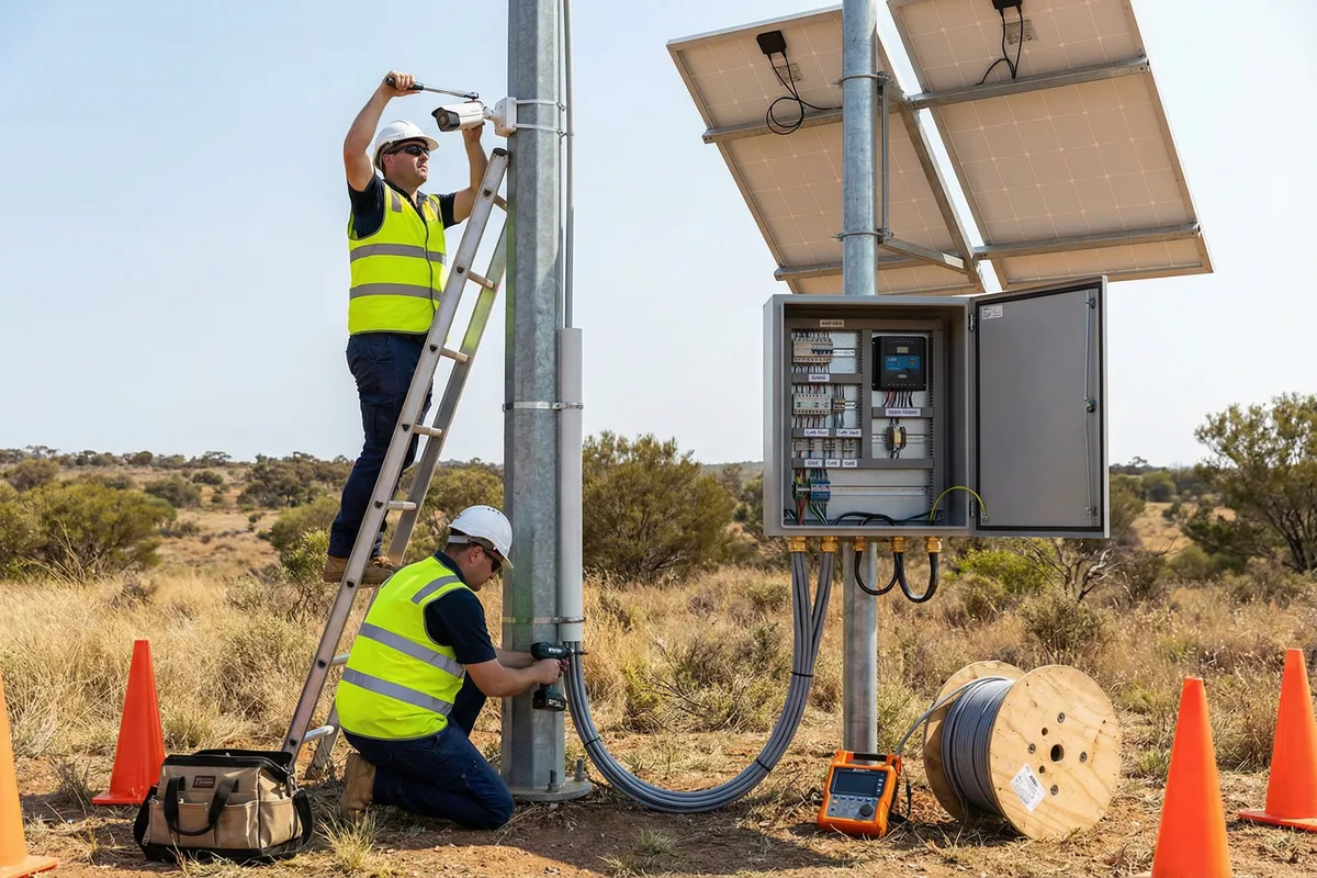
Figure 11.1: Professional installation in progress — Two technicians in high-visibility vests and hard hats: one mounting a bullet camera on a 6m galvanized steel pole using a torque wrench; one routing Cat6 cable through PVC conduit at the base. Open IP66 cabinet shows organized DIN-rail components, labeled cables, and solar charge controller. Safety cones, cable drum, and cable tester visible on the ground.
11.2 Pre-Installation Requirements
Before any physical installation work begins, the following pre-installation requirements must be verified. Failure to complete pre-installation checks is the leading cause of installation delays and rework.
| Requirement | Verification Method | Responsible Party |
|---|---|---|
| Site survey completed | Signed site survey report with GPS coordinates, photos, and coverage plan | Project Engineer |
| Foundation / pole base prepared | Concrete cured ≥28 days; anchor bolts at correct spacing; level within 2mm/m | Civil Contractor |
| Cable trenches excavated and inspected | Depth ≥600mm; sand bedding laid; route marked on as-built drawing | Civil Contractor |
| All equipment delivered and inspected | Delivery note signed; all items checked against BOM; no visible damage | Site Supervisor |
| Permits and access authorization | Landowner access permission; any required permits (height work, electrical) obtained | Project Manager |
| Safety briefing conducted | All technicians briefed on site hazards; PPE issued; emergency contacts posted | Site Supervisor |
| SIM cards activated and tested | SIM cards inserted in router; data connectivity confirmed with speed test | Network Engineer |
| IP address plan finalized | IP address assignment table completed; all devices assigned static IPs; no conflicts | Network Engineer |
11.3 Installation Sequence
The installation must follow the sequence below. Each phase must be completed and verified before the next phase begins. This sequence is designed to minimize rework by completing structural and civil work before electrical and network work, and by testing each layer before adding the next.
-
Pole Erection and Grounding SystemErect the galvanized steel pole; torque all anchor bolts to specification; install lightning rod at pole top; install down conductor; install ground ring and vertical rods; measure ground resistance (must be ≤4Ω before proceeding).
-
Cabinet Mounting and DIN-Rail AssemblyMount IP66 cabinet on pole at 1.5m height; install DIN-rail; mount all DIN-rail components (terminal blocks, SPDs, fuse holders, charge controller); install cabinet heater and thermostat; install desiccant sachets.
-
Solar Panel and Battery InstallationInstall solar panel mounting brackets; mount panels at correct tilt angle (latitude ± 15°); route DC cables in conduit; install DC SPD; connect battery bank with correct polarity; do NOT connect to charge controller yet.
-
Camera and Antenna MountingMount camera brackets at correct height and orientation; mount cameras; set initial aim angle; mount cellular antenna above cameras; route coaxial cable in conduit; install coaxial lightning arrestor at cabinet entry; seal all cable entries with cable glands and drip loops.
-
Cable Routing and TerminationRoute Cat6 cables from cameras to cabinet in conduit; terminate all cables at terminal blocks; label all cables at both ends; test all cables with cable tester before connecting to active equipment; route and terminate all DC power cables.
-
Network Equipment ConfigurationConfigure router: VLANs, firewall rules, VPN, cellular APN; configure PoE switch: VLAN assignments, port security; configure NVR: IP addresses, recording schedule, storage allocation, alarm settings; configure cameras: IP addresses, resolution, bitrate, motion detection zones.
-
Power-On and Initial TestingConnect solar charge controller to battery and panels; verify charging current; power on all equipment; verify DC bus voltage; check all SPD indicators; verify all devices obtain IP addresses; ping test all devices.
-
Camera Fine-Tuning and CommissioningView live feed from each camera; fine-tune aim, focus, and zoom; verify night vision at rated distance; configure motion detection zones; test alarm triggers; verify snapshot upload to cloud; run 24-hour soak test.
11.4 Common Issues and Debugging Guide
The table below provides a structured debugging guide for the most common issues encountered during installation and commissioning. For each symptom, the table lists the most likely causes in order of probability and the recommended diagnostic steps.
| Symptom | Most Likely Cause | Diagnostic Steps | Resolution |
|---|---|---|---|
| Camera not reachable on network | IP address conflict; wrong VLAN; cable fault; PoE budget exceeded | 1) Ping camera IP; 2) Check switch port VLAN; 3) Test cable with tester; 4) Check PoE budget | Reassign IP; correct VLAN; replace cable; upgrade switch |
| Blurry image | Focus not set; lens contamination; vibration; incorrect resolution setting | 1) Check focus ring; 2) Clean lens; 3) Check bracket tightness; 4) Verify resolution in camera settings | Adjust focus; clean lens; tighten bracket; correct settings |
| No night vision / IR not working | IR LEDs failed; IR cut filter stuck; incorrect night mode setting | 1) View camera with phone camera (IR visible to phone); 2) Check IR mode setting; 3) Check IR distance vs. actual distance | Replace camera if IR failed; adjust settings; reposition camera |
| VPN not connecting | SIM card not activated; APN incorrect; firewall blocking VPN port; VPN credentials wrong | 1) Test SIM with phone; 2) Verify APN setting; 3) Check router firewall; 4) Verify VPN credentials | Activate SIM; correct APN; open VPN port; correct credentials |
| Recording gaps | Network packet loss; HDD failing; NVR overloaded; storage full | 1) Check network packet loss; 2) Check HDD SMART status; 3) Check NVR CPU/memory; 4) Check storage remaining | Fix network; replace HDD; reduce camera count; increase storage |
| Battery not charging | Solar panel shading; DC SPD blown; charge controller fault; battery BMS fault | 1) Check solar panel voltage (open circuit); 2) Check DC SPD; 3) Check charge controller display; 4) Check battery voltage | Remove shading; replace SPD; replace controller; replace battery |
| Alarm not triggering | Motion detection zone not configured; sensitivity too low; camera not connected to NVR alarm input; NMS not configured | 1) Check motion detection zone in camera settings; 2) Test by walking in FOV; 3) Check NVR alarm input configuration; 4) Check NMS alarm settings | Configure zones; increase sensitivity; correct alarm input; configure NMS |
Safety Requirement: All electrical work must be performed with the system de-energized and locked out. Use the lockout/tagout procedure from Chapter 8 before working on any electrical components. Never work on the solar DC circuit without verifying that the panels are covered or the circuit is isolated — solar panels cannot be switched off and will produce voltage whenever illuminated.